Your Premier Source for High-Speed Optical Modules
SFP Optical Transceivers
Looking for high-performance optical transceivers? Your search ends with our factory. We specialize in producing a variety of high-speed optical modules, including QSFP28, QSFP-DD, and OSFP, known for their cost-effectiveness and superior performance. Our products are compatible with major brands and customizable to meet your specific needs.
Your Trusted Source for Optical Transceivers
THP stands out in the realm of SFP optical transceivers. Our specialty lies in offering customized solutions tailored to your unique needs. Whether it’s various form factors, transmission speeds, or wavelengths, our products are meticulously designed for precision and performance. These SFP transceivers are more than components; they’re the heart of your network’s reliability and efficiency.
1.25/10/25G Modules
1.25G SFP SX/LX/EX/ZX/BIDI
10G SFP+ SR/LR/ER/ZR/BIDI/DWDM
25G SFP28 SR/LR/BIDI
40/100G Modules
40G QSFP+ SR4/eSR4/PSM4/LR4/SWDM4
100G QSFP28 SR4/LR4/ER4/ZR4/SWDM4
100G QSFP DR1/FR1/LR1/ER1/BIDI
200/400/800G Modules
200G QSFP56 SR4/FR4/LR4/ER4
400G QSFP-DD SR8/DR4/FR4/LR4/ER4/ZR
400G/800G OSFP SR4/SR8
Customized SFP Optical Transceivers for Your Unique Projects!
At THP, we’re acutely aware of the intricacies in network communication technology. Our expertise lies not just in manufacturing SFP optical transceivers, but in crafting them to meet your precise needs. We recognize that every network is unique, and we are dedicated to providing SFP transceivers that align seamlessly with your specific requirements.
- Custom-Tailored Solutions: Our focus is on customization to suit your specific network requirements. Whether it’s data centers, enterprise networks, or ISP networks, we ensure our SFP transceivers are the perfect match for your project.
- Diverse Range of Options: We offer a variety of SFP transceivers, each designed to cater to different data rate requirements, distances, and wavelengths. This variety guarantees that you find the exact transceiver for your network’s unique demands.
- Flexible Data Rates and Distances: Our SFP optical transceivers come with varying data rate capabilities and transmission distances. This flexibility allows you to select the ideal transceiver for your network’s scale and speed requirements.
- Customizable Interface and Design: We understand the importance of aesthetics and integration. Our SFP transceivers can be customized in their physical design and interface, ensuring they not only perform excellently but also fit perfectly into your existing network setup.
At THP, we’re more than just a supplier; we’re a partner in your network’s success. We commit to ensuring that our SFP optical transceivers are not just components in your network, but the key to its efficiency, reliability, and excellence.
More Than Just an SFP Optical Transceiver Manufacturer
At THP, we see ourselves as more than just manufacturers of SFP optical transceivers. Our commitment to excellence transcends the usual boundaries of production. We pride ourselves on delivering exceptional customer service and support, distinguishing us in the field of network technology. Here’s a glimpse of what sets us apart when you choose THP as your partner:
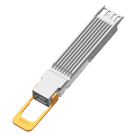
Innovative Transceiver Design
Looking for something beyond standard specifications? Share your vision with us, and we’ll bring it to life. Our design team is skilled in creating SFP optical transceivers that go beyond the catalogue, tailored to your unique network needs.

Customized Solutions
At THP, we specialize in crafting solutions that align precisely with your individual requirements. Whether it’s for data centers, enterprise networks, or telecommunications, we ensure our products are a perfect fit for your specific application.
Flexible Order Quantities
We understand the diverse needs and constraints of our clients. That’s why we offer flexibility in order quantities. Whether you’re starting small or scaling up, we cater to your requirements without minimum order constraints. Your needs, big or small, are our priority.

Comprehensive Support and Installation Assistance
Our commitment to you extends beyond the sale. Our team of experienced engineers is dedicated to ensuring your SFP optical transceiver integration is seamless. We provide comprehensive support and assistance, ensuring your network upgrade or installation is smooth and hassle-free.
At THP, we’re not just about selling products; we’re about building relationships and empowering your networks. Partner with us for an experience that redefines what it means to work with an SFP optical transceiver manufacturer.
Why is THP Your Go-To Source for SFP Optical Transceivers?
We know the value of specificity in the tech world. Our SFP optical transceivers are not just products; they’re solutions crafted for your specific business requirements. This customization extends to not just the technical specifications but also to the aesthetic aspects, ensuring a seamless integration into your existing setup.
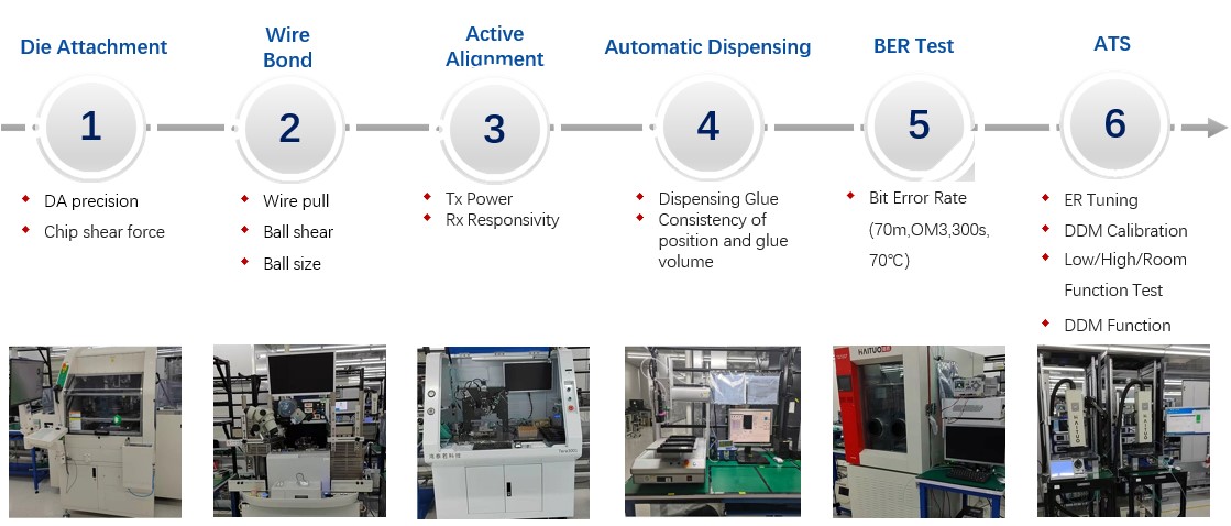
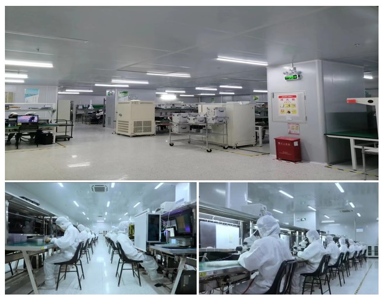
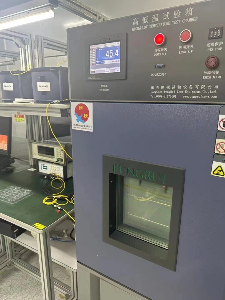
- How does THP ensure the quality of its SFP transceivers? Quality is our cornerstone. From rigorous testing to stringent quality control, every SFP transceiver from THP undergoes thorough inspection to ensure top-notch performance and durability. This means when you choose THP, you’re choosing a product that’s not just effective but also reliable.
- What sets THP’s SFP optical transceivers apart in the market? It’s our breakthrough technology. While others focus on standard specifications, we push the boundaries in innovation. Our transceivers are designed to be not only compatible with a wide range of devices but also to offer superior performance, setting new industry standards.
- How does THP cater to diverse customer needs? Our business model is centered around understanding and addressing the unique needs of each customer. Whether you’re a data center giant or a growing enterprise, our range of SFP transceivers is designed to meet your specific requirements.
- What about the efficiency and power consumption of THP’s SFP transceivers? In today’s world, efficiency is key. Our SFP optical transceivers boast low power consumption without compromising on performance, ensuring your networks run optimally while keeping energy costs in check.
In the dynamic world of optical communication, THP stands as your reliable partner, offering SFP optical transceivers that are not just components, but keystones in building efficient, high-performance networks. Join us in embracing the future of optical technology, today.
FAQs on SFP Optical Transceivers
How quickly can THP deliver SFP transceivers on an urgent basis?
We prioritize expedited shipping for urgent orders. Typically, we can dispatch products within 24-48 hours, depending on stock availability and order size.
What should I do if I receive a defective transceiver?
If you encounter a defective product, please contact us immediately. We’ll arrange for a replacement and handle all associated logistics promptly, as per our warranty and return policy.
Can THP transceivers be customized for specific wavelength requirements?
Absolutely! We offer customization for various wavelength requirements. Just provide us with your specifications, and our team will ensure your needs are met.
Are your SFP transceivers compatible with all major brands of networking equipment?
Our transceivers are designed for broad compatibility with most major networking equipment brands. We recommend providing your equipment details so we can confirm compatibility.
How can I track my order once it's been placed?
After placing your order, you’ll receive a tracking number. You can use this to monitor your order’s shipping status on our website or through the courier’s tracking system.
Does THP offer technical support for installation and troubleshooting?
Yes, we provide comprehensive technical support, including installation guidance and troubleshooting. Our technical team is available via phone, email, or live chat.
How does THP ensure the quality and reliability of its products?
Our products undergo stringent quality control processes, including performance testing and certification to international standards, ensuring high reliability and performance.
What payment methods does THP accept for international orders?
We accept various payment methods for international orders, including bank transfers, credit cards, and PayPal. Please contact our sales team for more details on specific payment options.
Your Comprehensive Guide to Purchasing
SFP Optical Transceivers
In the realm of network communication, Small Form-factor Pluggable (SFP) optical transceivers are indispensable components. Their role in efficiently transmitting data over fiber optic cables makes them a crucial element in modern networking. This guide aims to provide a thorough understanding of SFP optical transceivers and essential tips for purchasing the right type for your networking needs.
Table of Contents
Understanding Optical Transceivers
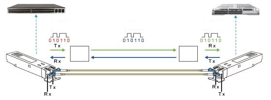
The working principle of optical transceivers
The appearance structure of optical transceivers
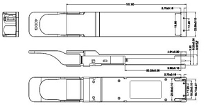
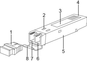
There are various types of optical transceivers, and their appearance structures are also different. However, the basic components of the structure include the following parts, as shown in the picture (taking SFP packaging as an example).
| ITEM | COMPONENT | FUNCTION |
|---|---|---|
| 1 | Dust cap | Protects the optical fiber connector, fiber adapter, optical interface of the optical module, and ports of other devices from external environmental pollution and external force damage. |
| 2 | Skirt | Ensures a good fit between the optical transceivers and the device optical interface, only exists in SFP packaged optical transceivers. |
| 3 | Label | Used to identify key parameters of the optical module and manufacturer information, etc. |
| 4 | Connector | Used for the connection between the optical transceiver and the board, signal transmission, and power supply to the optical transceiver. |
| 5 | Housing | Protects internal components, mainly including 1*9 housing and SFP housing. |
| 6 | Receiver interface (Rx) | Optical fiber receiving interface. |
| 7 | Transmitter interface (Tx) | Optical fiber transmitting interface. |
| 8 | Pull tab | Used for inserting and removing the optical module, and for easy identification, the colors of the pull tabs corresponding to different bands are also different. |
What are the key performance indicators of optical transceivers?
How to measure the performance indicators of optical transceivers? We can understand the performance indicators of optical transceivers from the following aspects.
- Average transmitted optical powerThe average transmitted optical power refers to the optical power output of the optical module’s transmitting end under normal working conditions, which can be understood as the intensity of light. The transmitted optical power is related to the proportion of “1” in the data signal being transmitted. The more “1” there are, the greater the optical power. When the transmitter sends a pseudo-random sequence signal, “1” and “0” roughly occupy half of the signal, and the power measured at this time is the average transmitted optical power, which is measured in units of W or mW or dBm. W or mW are linear units, and dBm is a logarithmic unit. In communication, we usually use dBm to represent optical power.
- Extinction RatioThe extinction ratio refers to the minimum ratio of the average optical power emitted by a laser under full modulation conditions when transmitting an all “1” code to the average optical power emitted when transmitting an all “0” code. It is measured in dB.When converting electrical signals into optical signals, the optical module emits laser light based on the input signal’s bit rate. The average optical power during an all “1” code represents the average power of the laser emission, while the average optical power during an all “0” code represents the average power when the laser is not emitting light. The extinction ratio represents the ability to differentiate between 0 and 1 signals and can be seen as a measure of the laser’s operational efficiency. The typical range for the extinction ratio is 8.2dB to 10dB.
- The center wavelength of the optical signalIn the emission spectrum, it refers to the wavelength corresponding to the midpoint of the line segment that connects the 50% maximum amplitude values. Different types of lasers or two lasers of the same type may have differences in center wavelength due to processes, production, and other reasons. Even the same laser may have different center wavelengths under different conditions. Generally, manufacturers of optical devices and optical modules provide users with a parameter, which is the center wavelength (such as 850nm), and this parameter is usually a range. Currently, the commonly used center wavelengths of optical modules are mainly in three bands: 850nm, 1310nm, and 1550nm.Why are these three bands defined? This is related to the fiber optic loss, which is the transmission medium of the optical signal. Through continuous research and experiments, it has been found that fiber optic loss generally decreases as the wavelength increases. The loss is minimal at 850nm, increases from 900nm to 1300nm, decreases again at 1310nm, and reaches the lowest point at 1550nm. The loss increases again above 1650nm. Therefore, 850nm is referred to as the short wavelength window, and 1310nm and 1550nm are referred to as the long wavelength windows.
- The overload optical poweralso known as saturation optical power, refers to the maximum average optical power that the receiving end component of an optical module can receive under certain bit error rate (BER=10-12) conditions. The unit is dBm.It should be noted that the photodetector may experience optical current saturation under strong light irradiation. When this phenomenon occurs, the detector needs a certain amount of time to recover. During this time, the receiver sensitivity decreases, and the received signal may be misjudged, resulting in bit errors. In simple terms, if the input optical power exceeds the overload optical power, it may cause damage to the equipment. Therefore, it is advisable to avoid strong light irradiation during operation to prevent exceeding the overload optical power.
- Receiver SensitivityReceiver sensitivity refers to the minimum average input optical power that the receiver component of an optical module can receive under a certain bit error rate (BER=10-12) condition. If the transmitted optical power refers to the intensity of the transmitter, then the receiver sensitivity refers to the intensity of the optical power that the optical transceiver can detect. The unit is dBm.In general, the higher the data rate, the poorer the receiver sensitivity, which means that the minimum received optical power is larger, and the requirements for the receiver components of the optical transceiver are higher.
- Received Optical PowerReceived optical power refers to the average optical power range that the receiving end component of an optical transceiver can receive under a certain bit error rate (BER=10-12) condition. The unit is dBm. The upper limit of received optical power is the overload optical power, and the lower limit is the maximum value of receiver sensitivity.In summary, when the received optical power is less than the receiver sensitivity, it may not be able to receive the signal properly because the optical power is too weak. When the received optical power is greater than the overload optical power, it may also not be able to receive the signal properly due to the presence of bit errors.
- Interface Rate The maximum telecommunications signal rate that optical devices can carry without error, as specified by Ethernet standards, includes: 125Mbit/s, 1.25Gbit/s, 10.3125Gbit/s, 41.25Gbit/s.
- Transmission DistanceThe transmission distance of optical modules is mainly limited by loss and dispersion. Loss refers to the loss of optical energy due to absorption, scattering, and leakage in the fiber during transmission. This energy dissipates at a certain rate as the transmission distance increases. Dispersion occurs because electromagnetic waves of different wavelengths propagate at different speeds in the same medium, causing different wavelength components of the optical signal to arrive at the receiving end at different times due to the cumulative transmission distance, resulting in pulse broadening and the inability to distinguish signal values.In terms of dispersion limitations for optical modules, the limited distance is much greater than the limited distance due to loss and can be disregarded. The limitation due to loss can be estimated using the formula: Limited distance due to loss = (transmit optical power – receiver sensitivity) / fiber attenuation. The attenuation of the fiber is strongly correlated with the actual fiber used.
Classification of Optical Transceivers
To meet the demand for various transmission rates, different speed optical modules have been developed, including 800GE optical transceivers, 400GE optical transceivers, 100GE optical transceivers, 40GE optical transceivers, 25GE optical transceivers, 10GE optical transceivers, GE optical transceivers, and FE optical transceivers.
The higher the transmission rate, the more complex the structure, resulting in different form factors. The form fators suitable for Huawei switches include: QSFP-DD, QSFP28, QSFP+, SFP28, SFP/eSFP, SFP+, CXP, CFP, etc.
How to understand the naming of optical transceivers?
Understanding the naming rules of optical transceivers allows you to read all the information contained in the product names of manufacturers. This article explains the decomposition based on the general naming rules.

A refers to the form factors, which mainly includes:
SFP/eSFP, SFP+, SFP28, QSFP+, CXP, CFP, QSFP28, QSFP-DD
B refers to the data rate like:
FE, GE, 10GE, 25GE, 40GE, 100GE, 400GE
D refers to the transmission distance of optical transceivers, which is measured in kilometers
E is decided by the type of fibers used.
F means the wavelength measured by nm
The main reasons for the failure of optical transceivers and protective measures
- Operating instructions
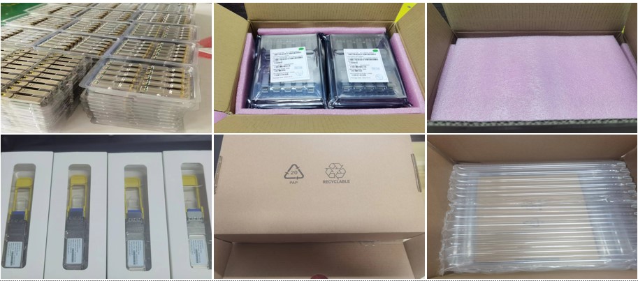
- During the transportation and transfer process before using the optical transceiver, it must be kept in an anti-static packaging and should not be taken out or placed randomly.
- Before handling optical transceivers, it is necessary to wear anti-static gloves and anti-static wristbands, and take anti-static measures when installing optical devices (including optical modules).
- Testing equipment or application equipment must have a good grounding wire.
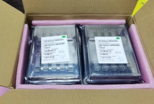


- Operating Instructions
- Handle the optical transceiver with care to prevent dropping.
- When inserting the optical transceiver, use your hand to push it in and do not use other metal tools. When removing it, first open the pull ring to the unlock position and then pull the pull ring. Do not use other metal tools.
- Please use a dedicated cleaning swab for cleaning the optical port and do not insert any other metal objects into the optical port.
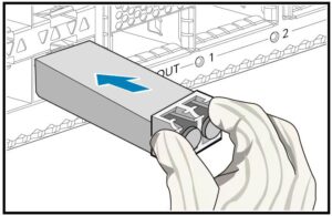

Case Study - How to solve the problem of low or high optical power?
					BASETRAP_1.3.6.1.4.1.2011.5.25.129.2.17.1 hwOpticalPowerAbnormal        // the transmit or receive power of the optical module is abnormal
BASETRAP/3/OPTPWRABNORMAL: OID [oid] Optical module power is abnormal. (EntityPhysicalIndex=[INTEGER], BaseTrapSeverity=[INTEGER],
 BaseTrapProbableCause=[INTEGER], BaseTrapEventType=[INTEGER], EntPhysicalContainedIn=[INTEGER], EntPhysicalName="[OCTET]", Relati
veResource="[OCTET]", ReasonDescription="[OCTET]")

ENTITYTRAP_1.3.6.1.4.1.2011.5.25.219.2.4.5 hwOpticalInvalid 136193   //high optical power alarm
ENTITYTRAP_1.3.6.1.4.1.2011.5.25.219.2.4.5 hwOpticalInvalid 136194   //low optical power alarm
ENTITYTRAP_1.3.6.1.4.1.2011.5.25.219.2.4.5 hwOpticalInvalid 136195   //high optical power alarm
ENTITYTRAP_1.3.6.1.4.1.2011.5.25.219.2.4.5 hwOpticalInvalid 136196   //low optical power alarm
ENTITYTRAP/3/OPTICALINVALID:OID [oid] Optical Module is invalid.(Index=[INTEGER], EntityPhysicalIndex=[INTEGER], PhysicalName=\"
[OCTET]\", EntityTrapFaultID=[INTEGER])
Fault Phenomenon
Optical Power Alarm
Possible Causes
- Inconsistent models and wavelengths of optical modules at both ends.
- The optical module is not inserted tightly or there is a fiber fault.
- The fiber is too long or the link loss is too high.
- Abnormal transmitting power at the opposite end.
- Optical module failure.
Troubleshooting Steps
- Ensure that the wavelengths of the optical modules are consistent. Execute the “display transceiver [interface interface-type interface-number | slot slot-id] [verbose]” command to display the optical module information on the device interface. The “Wavelength(nm)” field in the echo information indicates the wavelength of the optical wave. If they are inconsistent, replace the optical module.
- Check if the link connection is normal. Reinsert the fiber and optical module to determine if it is due to poor contact. Also check if the fiber connector is damaged or contaminated, and handle or replace it in a timely manner.
- Check the length of the fiber. The length of the fiber should be less than the transmission distance supported by the optical module. Users can shorten the fiber length or replace it with an optical module that supports a larger transmission distance based on the actual situation of the network.
- Check the transmitting power at the opposite end. Check the transmitting power parameters of the opposite end device to ensure that it exceeds the lower threshold of the transmitting power.
- Check if the optical module and fiber match.
- Check the model and manufacturer of the optical module. Check if the local and opposite end devices use optical modules of different manufacturers with the same model. If the interconnected optical modules are on the same wavelength and the transmission distance is not long, but there are high or low optical power alarms, it may be due to the use of optical modules of different manufacturers with the same model. Although the wavelengths of the optical modules are consistent, the different designs of each manufacturer result in different optical power indicators of the optical modules themselves, leading to power alarm phenomena during docking. Users can replace the optical module with a product from the same manufacturer.
- Replace the device. If the problem cannot be determined even after performing a loopback test with a short fiber, consider replacing the optical module and fiber as a priority.
Revolutionize Your Network with Superior SFP Optical Transceivers!
Unlock the potential of your network with THP’s cutting-edge SFP optical transceivers.


